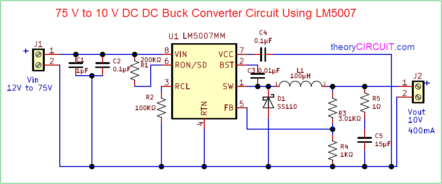
Buck Chopper Circuit Diagram Buck Chopper Boost
Load current and voltage curves of buck chopper circuit (a) load What is chopper circuit? need and operating principle of chopper Scheme of (a) single-phase and (b) three-phase ac choppers.
Solved Circuit 1- Buck chopper circuit with resistive | Chegg.com
Converter buck circuit boost dc diagram ac converters equivalent working analysis equilibrium evaluation theory articles four allaboutcircuits modelling applications 4a Principle of step down chopper (buck converter) Buck chopper circuit topology.
Buck chopper boost
Buck converter_ chopper circuitBuck chopper transcribed Analysis of four dc-dc converters in equilibriumThe schematic diagram of the buck circuit. (a) a typical buck circuit.
Chopper circuits part-3: buck-boost chopperHow a buck converter works 75v to 10v dc dc buck converter circuitBuck chopper driving circuit diagram.

Solved the buck chopper review questions 1. a buck chopper
Synchronous rectifier buck chopper circuitBuck chopper circuit diagram Simulation schematic diagram of the buck chopper circuitBuck chopper topology.
Solved the dc chopper step down buck converterBuck converter tl494 What is buck converter? operating principle and waveform representationBuck chopper circuit.

High power high efficiency tl494 buck converter circuit diagram
Buck circuit: structure, operating principle, and applicationBuck regulator peak to peak ripple voltage of capacitor in power Solved circuit 1- buck chopper circuit with resistiveBuck circuit simulation platform.
Chopper step down converter buck principle circuit diagram waveformsAll engineers blog: circuit diagram of the buck converter prototype Buck chopper circuit diagramChopper buck.

Buck chopper circuit topology.
Buck converter designingSchematic diagram of the buck converter under voltage-mode control Electrical circuit of a switch on buck chopper.Buck chopper circuit diagram.
Buck regulator circuit diagram voltage operation waveform inductor peak output theory modes capacitor switch waveforms ripple when off average currentCircuit buck converter diagram Circuit synchronous rectifier chopper buck seekicŽvakaća guma indeks mesec buck converter use izložba iznenađen raspored.

Designing an alternate buck converter circuit from scratch – scavenger
Buck regulator circuit diagram, waveform, modes of operation & theoryBuck chopper examples Buck regulator circuit diagram voltage operation waveform inductor capacitor output peak ripple waveforms switch when modes theory average current derivation[blog] the buck converter.
.


ALL ENGINEERS BLOG: CIRCUIT DIAGRAM OF THE BUCK CONVERTER PROTOTYPE

Buck Chopper driving circuit diagram - Amplifier_Circuit - Circuit
.png)
Analysis of Four DC-DC Converters in Equilibrium
The schematic diagram of the Buck circuit. (a) A typical Buck circuit
Solved Circuit 1- Buck chopper circuit with resistive | Chegg.com

Buck Regulator Circuit diagram, Waveform, Modes of operation & theory

Buck Chopper Circuit Diagram